

1 Liquid Controls ® Positive Displacement Meters and Accessories Product Overview 100-10 www.lcmeter.com 2 Features and Benefits LC meters are exclusively engineered with no metal-to-metal contact within the measuring chamber, making use of a thin liquid capillary film between rotating and stationary components for hydraulic sealing. This unique design results in minimal wear, sustained accuracy, and low operating costs. When measuring the flow of a broad range of products, LC’s innovative design results in minimal resistance to flow and the ability to operate on pump pressure or gravity feed. That means efficient performance and low pressure drop across the meter. LC’s combination of low pressure drop with minimum seal or slippage area offers better accuracy over a wide range of flow than other commercially produced PD meters. Liquid Controls is a world renowned supplier of reliable, high-accuracy, positive displacement (PD) metering systems. Whether your business requires flow measurement for custody transfer or process control, with an LC PD meter on your delivery vehicle, at your bulk shipping facility, or at your plant, you’ll get years of consistently accurate, trouble-free service. Because of the ease of installation, minimal maintenance, and few replacement parts, you’ll appreciate the low cost of owning and operating LC positive displacement meters. Premier products, premier performance Truck Metering • Refined fuels • LPG • Aviation fuel • Alternative Fuels • Lube oils • Agricultural chemicals Bulk Plant/Terminal Metering • Crude petroleum products • Refined petroleum products and LPG • Alternative Fuels • Industrial chemicals/solvents • Marine fuel/bunker oil • Hot asphalt/Asphalt emulsions Dispenser metering • LPG and diesel fuel Industrial process metering • Liquid sweeteners/corn syrup • Paints and coatings • Pulp and paper • Pharmaceuticals • Printing inks • Concrete add mixtures • Industrial liquids Applications LC’s three-rotor positive displacement measuring chamber. The simplicity in design and high quality manufacturing make LC meters more reliable and less costly to operate than other meters. Multiple installation configurations provide greater mounting versatility. In many cases, you can replace your existing meter with an LC meter with minimal disruption to system piping and components. 3 End cover Timing gear set Bearing plate Rotor set O-ring seal Measuring chamber System accessories Liquid Controls’ innovation extends beyond meters to system components and accessories. Precision-engineered and manufactured LC strainers, air eliminators, and valves provide unsurpassed performance across a wide range of liquids and applications. LC meters are also available with your choice of mechanical or electronic registers. Our state-of-the-art family of LectroCount™ electronic registers provide your meter with automated control and data management capability to improve productivity, lower your costs, and increase your profits. The unique design of the LC positive displacement meter results in minimal wear and a long, accurate service life. At Liquid Controls’ ISO-certified facility in Lake Bluff, Illinois, LC metering systems are manufactured to last. Meters crafted with quality decades ago are still in operation today. Our metering systems are sold and serviced by a worldwide network of qualified distributors and OEMs. They’re backed by our reputation for quality, accuracy, and reliability. That’s why Liquid Controls continues to lead the industry in Weights and Measures-approved custody transfer metering, and why you’ll want your business to include Liquid Controls products. The LC metering element • Provides custody transfer accuracy • Performs well with a wide range of liquids, from low viscosity to high viscosity • Minimizes inaccuracies due to clearance changes and wear common to other meter designs • Performs with equal accuracy when flow is in either direction (forward or reverse) • Operates without axial thrust on rotor bearings for longer life • Adapts to multiple installation positions • Includes Weights and Measures approvals, worldwide Linearity (over 10:1 range) Capable of ±0.10% (electronic registration) Capable of ±0.22% (mechanical registration) Repeatability Capable of 0.02% For complete specifications, refer to page 8. 4 LC meters are known worldwide for exceptional accuracy, reliability, and longevity in a broad range of applications. From truck applications metering refined petroleum products and LPG, to process applications metering a wide range of industrial liquids. Truck meters For custody transfer applications requiring Weights and Measures-approved accuracy, Liquid Controls M and MA Series truck meters provide the industry’s most time-proven and respected records of superior value and performance. LC truck meter accessories include air eliminators, strainers, valves, and a choice of mechanical or electronic registers and printers for presetting, totalizing deliveries, and printing tickets. Typical applications of the LC meter and accessories include tankwagons delivering fuel to homes for domestic heating or gasoline to service stations; bobtails delivering LPG to homes and farms; and aviation refuelers delivering avgas or jet fuel into aircraft. Other applications include metering of anhydrous ammonia and other farm-related products from vehicle-mounted tanks. Meters M-7 with electronic registration for refined fuels (with E-7 valve, optical air eliminator, and high-capacity air eliminator) MA-7 with electronic registration for LPG M-25 with mechanical counter and printer M-30 with electronic registration for aviation fuel Common truck meter model numbers Application Description Model Refined fuels 2″, 100-GPM aluminum-body meter with strainer/air eliminator, backcheck valve, preset valve, electronic register, and printer M-7-CLI-1/LCR-II Liquified petroleum gas (LPG) 2″, 100-GPM aluminum-body meter with strainer/vapor eliminator, inlet backcheck valve, differential valve, electronic register, and printer MA-7-CLI-10/LCR-II Aviation fuel 3″, 300-GPM aluminum-body meter with register and printer M-25-E-2 MSA meter skid with Toptech SMP controller 5 Bulk plant and loading terminal meters The larger sizes of M and MS Series meters are ideal for bulk measurement of product during loading and unloading of tanks, transports, railcars, ships, barges, and more. The MS Series meters are housed in a spherical steel case for higher system pressure applications up to 1,440 PSI. MS Series spherical case meters provide the ruggedness, accuracy, and selection of inlet/outlet configurations to handle nearly any bulk metering requirement. Meter accessories include bulk air/ vapor eliminators, strainers, valves, and mechanical or electronic registers. Turbine meters in many sizes are also available for loading terminal applications where small size due to limited available space is a consideration in meter selection. Skid systems are designed to accommodate all necessary ancillary equipment including strainers, air eliminators, valves, and a selection of mechanical or electronic registers and load computers. Systems come fully piped and ready for installation and field calibration. Prover systems are also available built to customer specifications. Contact the factory for complete details. MS meter with electronic registration and strainer Turbine meter with IT400 M-30 with POD Common load rack/terminal meter model numbers Application Description Model Refined fuels 3″, 350-GPM spherical-case meter with strainer/air eliminator, valve, and register MS-30-K-1 4″, 700-GPM spherical-case meter with strainer/air eliminator, valve, and register MS-75-K-1 6 LPG and diesel fuel dispenser meters Liquid Controls manufactures meters specially designed for high speed diesel fuel dispensers for refueling trucks as well as a meter specially designed for LPG autogas dispensers.

High speed diesel dispenser meter The high speed diesel dispenser meter is rated for flow rates from 12 to 60 GPM and is widely applied in diesel dispensers manufactured by a number of dispenser OEMs. Long operating life, minimal maintenance, and sustained accuracy make it the meter of choice for this demanding OEM application. LPG autogas dispenser meter The MA-4 meter is specially designed for LPG autogas dispensers. It is available in two configurations: a single meter design for dispensers with one delivery hose, and a dual meter design for dispensers with two delivery hoses. The efficient, dual meter unit economizes space by utilizing a single strainer/vapor eliminator for both meters, and incorporates an integrally mounted differential valve on top of each meter. Meters are available with electronic temperaturevolume compensation. The flow range for the MA-4 LPG dispenser meter is 2.5 to 40 GPM. Regulatory approvals include NTEP, NFPA 58, and UL 25. Hazardous Location Rating is Class I, Division 1, Group D (LPG). MA-4 LPG dispenser meter, single MA-4 LPG dispenser meter, dual Common dispenser meter model numbers Application Description Model Diesel dispenser 2″, 60 GPM diesel dispenser meter M-5 LPG autogas dispenser 1″, 40 GPM LPG dispenser meter (single) MA-4 1″, 40 GPM LPG dispenser meter (dual)† MA-4 †Maximum flowrate for both meters (combined) is 40 GPM Meters 7 Industrial/process meters Liquid Controls PD meters in aluminum, stainless steel, brass, and cast iron provide the necessary accuracy for batch processing, flow rate control, blending, and custody transfer of liquids across a broad range of products, viscosities, temperatures, and pressures. Meters can be supplied with mechanical counters and registers, or they can be optionally outfitted with the LC POD electronic pulser for compatibility with Liquid Controls LectroCount electronic registration systems or other scalable, pulserdriven counters, batch controllers, or flow computers. Liquid Controls meters can be easily specified to include an assortment of process connections including ANSla flange, slip-on weld flange, or NPT or BSPT threads. Popular applications in the food industry include metering liquid sweeteners such as corn syrup or vegetable oils. In the industrial market, applications include metering solvents, acids, caustics, and water. Always contact the factory or refer to Engineering Data Publication 400-10 for specific recommendations. a ANSI flanges only available for M-5, M-7 Class 8, and M30 Class 7, 27, and 37 meters. Stainless steel M-7, class 8 meter with POD pulser Common process meter model numbers Application Description Model Solvents 2″, 100-GPM aluminum meter with counter M-7-A-16 Liquid sweeteners 2″, 100-GPM aluminum meter with counter M-7-A-3 Acids 2″, 80-GPM 316 stainless steel meter with counter M-7-A-8 Caustics 2″, 100-GPM cast iron meter with counter M-7-A-7 Model Metallurgy Application class see table on page 9 M-5, 7; MSAA-7, 15, 30, 120 Stainless steel 8 M-7, 30 Cast iron 7, 27, 37 MS/MSAA/MSA/MSB/MSC-7, 15, 30, 75, 120 Steel 1, 2, 10, 14, 16, 37b b MS-7 only 8 Construction Meter housing M Series: aluminum, brass, cast-iron or stainless-steel MS Series: steel case (elements by class), or stainless steel (epoxy-coated steel available for aviation and other applications) Meter element and rotors Cast aluminum (other metallurgies available including cast iron and stainless steel) Internal components Aluminum, Ni-Resist, stainless steel, iron Seal materials UL recognized component: Buna-N, Viton®, PTFE® Bearings Carbon, PTFE®, Ni-Resist Viton® and PTFE® are registered trademarks of DuPont Corporation. Victaulic® is a registered trademark of Victaulic Company. Specifications LC meters meet NTEP (NIST Handbook 44) and many International Weights and Measures accuracy requirements, as well as U.S. Military specifications. Accuracy/Performancea Repeatability Capable of 0.02% or better at any flow rate over entire range Linearity • Over 5:1 range Mech. registration: capable of ±0.125% or better from max. nom. flow rate Elect. registration: capable of ±0.10% or better from max. nom. flow rate • Over 10:1 range Mech. registration: capable of ±0.22% or better from max. nom. flow rate Elect. registration: capable of ±0.10% or better from max. nom. flow rate • Over 40:1 range Mech. registration: capable of ±0.5% or better from max. nom. flow rate Elect. registration: capable of ±0.15% or better from max. nom. flow rate Temperature range -40 to 160ºF (-40 to 71ºC) For higher temperature applications, consult factory. a Stated accuracy obtainable when all variables remain constant. Reading/measurements reflect a minimum of one minute of flow at selected rate(s). All accuracy statements based on metering safety solvent (aliphatic hydrocarbon), approximate viscosity 1 CPS. On higher viscosity products, the average deviation in accuracy will be less. 9 Maximum nominal flow rateb Flange size Maximum non-shock working pressurec Construction classes/ typical application see descriptions below GPM L/min m³/hr 150 PSI 10.5 BAR 275 PSI 19 BAR 300 PSI 21 BAR 350 PSI 24 BAR 720 PSI 50 BAR 1,440 PSI 100 BAR 40 151 9 1″ MA-4 10 60 227 14 1½”, 2″ opt. M-5 M-5d MA-5 1, 2, 3, 4, 8, 10, 14, 16, 30 100 380 23 2″, 1½” opt. M-7 M-7d MA-7 1, 2, 3, 4, 7, 8e , 10, 12, 14, 15, 16, 27, 37 100 380 23 2″, 1½” opt. MS-7 MSAA-7 MSA-7 MSB-7 MSC-7 1, 2, 7, 10, 14, 16, 37 150 570 34 2″ M-10 M-10d 1, 2 200 757 45 3″ M-15 M-15d MA-15 1, 2, 3, 4, 10, 14, 15, 16 200 757 45 3″ MS-15 MSA-15 MSA-15 MSB-15 MSC-15 1, 2, 8, 10, 14, 16 301 1,140 68 3″ M-25 M-25d 1, 2 348 1,320 79 4″, 3″ opt. M-30 1, 2, 3, 4, 7, 14, 15, 16, 27, 37, 47 350 1,325 79 3″, 4″ opt. MS-30 MSAA-30 MSA-30 MSB-30 MSC-30 1, 2, 8, 10, 14, 16 450 1,700 102 4″, 3″ opt. M-40 1, 2 450 1,700 102 3″, 4″ opt. MS-40 1, 2 600 2,271 136 4″, 6″ opt. M-60 M-60d 1, 2, 3, 14, 15 700 2,650 159 4″ MS-75 MSAA-75 MSA-75 MSB-75 MSC-75 1, 2, 10, 14 800f 3,000 182 6″, 4″ opt. M-80 M-80d 2 1,000 3,785 227 6″ or 8″ MS-120 MSAA-120 MSA-120 MSB-120 MSC-120 1, 2, 8, 10, 14 LC meter selection (by flow rate – NIST Standard)a a Standard LC meters (with the exception of the M-10, M-25, M-40 and M-80) are suitable for operation on products with viscosities up to 1,000,000 SSU. b Aluminum-body meters are suitable for intermittent overspeed operation at 125% of rating for clean, lubricating fluids. Consult the factory for details. c Maximum, non-shock working pressure ratings are based on products at temperatures below 160ºF (71ºC). Consult the factory for pressure ratings at elevated temperatures. d 275 working pressure available for meter only. e Recommended operation for Class 8 meters should not exceed 80% of maximum rated capacity. Recommended maximum flowrate may be less depending on viscosity. f M-80 Class 2 meter may be operated at flow rates up to 1,000 GPM for a limited period of time on jet fuel only. Class 1 Refined petroleum products, biodiesel Class 2 Aviation and jet fuel Class 3 Variety of products including: liquid sugars, sweeteners, syrups, vegetable oils Class 4 Treated waters and solvents where no red metals are allowed Class 7 Chlorinated solvents, ethanol Construction/application classes Class 8 Acid pH liquids including: nitric, phosphoric, glacial acetic acids, citric juices, vinegar, ethanol Class 10 Liquified petroleum gas (LPG) Class 12 Anhydrous ammonia (NH3) Class 14 Crude oil, heated products, viscous liquids Class 15 Oil- or water-based latex products, polyester resins, adhesives, herbicides, nitrogen fertilizers Class 16 General solvents, 200 proof alcohol, ethanol Class 27 Alkaline pH liquids: latex products, adhesives, liquid fertilizers Class 30 Herbicides Class 37 Sodium hydroxide solutions, high sulfur crude oil, alkaline pH liquids Class 47 Mildly abrasive liquids 10 Meter registration equipment Liquid Controls provides a choice of Weights and Measures-approved mechanical or electronic registration, ticket printing, and control systems for truck-mounted or fixed-site meter applications. Both technologies provide recording functions for totalizing, inventory control, billing, batching, and ticketing. Electronic registration Liquid Controls’ family of LectroCount™ electronic registers provide near-perfect metering accuracy over a full range of flow rates and deliver enhanced functions including: automated data collection (e.g., date, time, product selection, delivery quantity, and more), on-site ticket generation, meter linearization, electronic temperature volume compensation, and improved security. LectroCount™ electronic registers—Compatible with virtually all flow meters, the family of NEMA 4X LectroCount electronic registers is UL Class I listed and Weights and Measures approved. A simple “Run,” “Stop,” “Print” selector switch makes product delivery easy. The LectroCount LCR 600 can be upgraded to provide point-ofsale and aviation fueling functions. LectroCount is optionally available with electronic temperature volume compensation, whch eliminates the effect of product temperature change on measured volume. LectroCount Data Management System (DMS)—The DMS is an in-cab data management system designed for fuel delivery vehicles with LectroCount registers. There are three types of application software available for the DMS, each one tailored to the intricacies of a specific fueling application: DMS Delivery for customer-direct, point-ofsale fuel delivery, EZConnect for fleet fueling, and FlightConnect for aviation fueling. Differential Pressure (DP) Transducer—A safety shutdown device and maintenance tool for aviation fueling. Maximum differential pressure (across the full flow fuel monitor or filter separator) and the corresponding flow rate are printed on the ticket. LectroCount LCR 600 LectroCount LCR-II XL LED Remote Display—Perfect for aviation refuelers, load racks, and other applications in vast spaces where long-distance viewing is necessary, the six 2¼” high digits, each consisting of 18 red LED lights, are discernible from up to 250 feet away. Pulse output device—Converts the rotary motion of Liquid Controls flowmeters into a high resolution, unscaled pulse stream. No dynamic seals to fail or leak. The POD’s pulse stream is accepted by LectroCount registers and a wide variety of other electronic monitoring devices and control equipment. 11 Mechanical registration Mechanical registers have traditionally been used in a variety of mobile and fixed-site applications. Mechanical registers are ideal for applications without electrical power and can be installed on virtually all LC meters. Mechanical counter with ticket printer—Large-numeral counter provides 5-digit resettable and 8-digit non-resettable totalizers. Printer generates an imprinted record of the transaction which is legal for use in resale applications. Mechanical preset counter—Available for either single-stage or two-stage valve closure. Sets a predetermined volume and controls a mechanically linked valve. Optional microswitches convert mechanical motion to an electronic signal for control of remotely located valve, pump, and alarms. Counter-mounted pulser—Supplies an electrical signal to remote totalizers, batch controllers, rate-of-flow recorders, etc. Pulser models include dry reed (1 or 10 pulses per revolution), solid state single channel (100 pulses per channel) or solid state quadrature (50 pulses per channel). Mechanical rate-of-flow indicator—Direct-reading dial providing instantaneous response and dependable accuracy to within 1% of flow rate through meter. Cast aluminum case with ball bearings throughout. Readouts available in gallons, liters, and dekaliters per minute. Mechanical temperature volume compensator—Uses a fluid-filled capillary system to sense product temperature and automatically correct counter reading for product volume changes due to temperature. When the temperature is 60º F, a 1:1 output ratio is supplied to the register. Output ratio is adjusted upward or downward depending on temperature fluctuation around 60º F. Printers—For all mobile and stationary applications from –22 to 158ºF (–30 to 70ºC). Printers generates an imprinted record of the transaction which is legal for use in resale applications as well as multiple copies of delivery tickets, diagnostic tickets, calibration reports, and shift tickets. 12 Accessories air/vapor eliminators and strainers Liquid Controls provides a variety of precision-engineered accessories including strainers, air and vapor eliminators, and valves designed to ensure that your measuring system performs accurately and trouble-free from startup and through the long service life of the equipment. Costly measuring inaccuracies or maintenance problems can result whenever air, vapor, rust, scale, or other foreign materials are introduced into the flow of liquid. Air/vapor eliminators Air and vapor eliminators are installed on the inlet side of the meter in order to maintain high-accuracy liquid measurement. The combination of an air eliminator with a downstream differential valve or air check valve minimizes the passage of air or vapor through the meter. The mechanical LC air eliminator consists of a housing that contains a float assembly in combination with flexible reed strips and two orifice plates to control elimination of free air or vapor. Air/vapor elimination is required for Weights and Measures regulatory approvals in custody transfer applications. The optical air eliminator, developed by Liquid Controls, is available for use with M-5, M-7, M-10, M-15, and M-25 meters for refined petroleum products. This system features optical sensing for liquid level detection and no moving parts for optimal field performance. The optical vapor eliminator, also developed by Liquid Controls, is available for LPG applications. Metallurgy Pressure rating Used with Aluminum 150 PSI M-5, 7, 10, 15, 25, 30, 40, 60 meters F-7, 15, 30 strainers (petroleum) High pressure aluminum 350 PSI MA-4, 5, 7, 15 meters FA-7, 15 strainers (LPG) Cast iron 150 PSI M-7 meters F-7 strainers (chlorinated solvents & alkaline liquids) Stainless steel 150 PSI M-5, 7 stainless steel meters F-7 stainless steel strainers (acidic solutions) Steel 300 PSI MS, MSA and MSAA Series meters FS, FSA and FSAA Series strainers (MS series) Bulk plant 150 PSI M and MS Series meters (Choice of 3”, 4”, 6” and 8” flange connections) Stainless steel body High pressure aluminum body Optical air eliminator aluminum body Mechanical air eliminator (float activated) Optical air eliminator (no moving parts) Steel body Cast iron body Bulk plant air eliminators Single head (shown) and dual head models available. Single head also available with optical sensor. Valve Meter Strainer Air/vapor eliminator Electronic register Reed strips (2) Valve plate Valve plate Venting port Solenoid valve Vent Optical Sensor Venting port Float Typical construction details 13 Aluminum body Cast iron or stainless steel body Steel body for bulk plant systems High-capacity strainer with air eliminator (available with optional outlet backcheck valve) Strainer basket Strainers Strainers are always recommended for application on the inlet side of the meter to help protect against damage caused by foreign particles in the liquid: e.g., rust, pipe scale, and burrs from new piping installations. Although strainers extend the service life of the meter once in operation, systems should always be flushed and completely free of foreign material before meter installation and startup. Strainer body metallurgies include aluminum, cast iron, brass, and stainless steel. Model Metallurgy Flange size Pressure rating Used with F-7 Aluminum 2″ 150 PSI M-5, M-7 FA-7 Aluminum 2″ 350 PSI MA-5, MA-7 F-7 Cast iron 2″ 150 PSI M-7 F-7 Brass 2″ 150 PSI M-7 F-7 Stainless steel 2″ 150 PSI M-5, M-7 F-15 Aluminum 3″ 150 PSI M-15, M-25 FA-15 Aluminum 3″ 350 PSI MA-15 F-30 Aluminum 4″ 150 PSI M-30, M-40, M-60 FS Series Steel 2, 3, 4 and 6″ 150 PSI MS Series meters FSAA Series Steel 2, 3, 4 and 6″ 275 PSI MSAA Series meters FSA Series Steel 2, 3, 4 and 6″ 300 PSI MSA Series meters High capacity strainers/air eliminators A high capacity strainer/air eliminator with optional check valve is highly recommended for metering refined fuels (gasoline, fuel oil, etc.) off tank wagons for custody transfer applications. The unit installs directly to the meter inlet and facilitates passing U.S. and Canadian Weights and Measures split compartment testing. Unit uses standard 100-mesh strainer basket (3” size). Model Flange size Pressure rating Used with F-7 (Hi-cap) 2″ 150 PSI M-7, M-10 F-15 (Hi-cap) 3″ 150 PSI M-15, M-25 Strainer baskets The proper strainer basket to use depends on the product and the viscosity of the product over the expected range of metering temperatures. The following table provides general application guidelines. Consult the factory for special recommendations. Strainer mesh size General application 200M LPG, only 150M LPG, standard 100M Gasoline, solvents, LPG 80M Gasoline (alternate), solvents 40M Heating oil, diesel fuel, light oils 20M Motor oils and other viscous products 14 Accessories valves Valves Liquid Controls valves are designed for a wide range of applications, flow rates, and minimum head loss. Careful engineering and construction ensure smooth, accurate, and controlled operation. LC valves offer the important advantages of time-tested reliability and leak-tight shutoff. V- and VS-Series piston valves for refined petroleum products and industrial liquids The V-Series mechanically actuated piston valves are available in 2” through 4” sizes and are designed for mounting on the meter outlet to provide tight shutoff with smooth and easy operation regardless of system line pressure. Valves may be manually operated or connected via a mechanical linkage to a preset counter on the meter for single stage closure, or two-stage closure to eliminate hydraulic shock. Valves are indexable in 90° increments for up, down, or side facing outlet. E-7 solenoid operated control valve with flow switch for refined petroleum products The E-7 Series solenoid-operated control valves are installed at the meter outlet and are designed especially for use with Liquid Controls electronic registers. These solenoid operated piston valves can be applied for either single or two-stage closure. The flow control switch switches the pump between low bypass and high bypass mode. Valves provide compact installation and are indexable in 90° increments for up, down, or side facing outlet. Model Body materiala Used with (Meter) Companion flanges (NPT, BSPT, and slip weld) Maximum capacity Working pressure Application class* E-7 A2900 Series Aluminum M-5, M-7, M-10 11/2″ and 2″ 150 GPM (550 L/min) 150 PSI 1 V-7 A2600 Series Aluminumb M-5, M-7, M-10 11/2″ and 2″ 150 GPM (550 L/min) 150 PSI 1, 2, 3, 4, 14, 15, 16, 30 V-15 A3600 Series Aluminum M-15, M-25 3″ 300 GPM (1,136 L/min) 150 PSI 1, 2, 3, 4, 14, 15, 16 V-30 A4600 Series Aluminum M-30, M-40, M-60 4″ 600 GPM (2,271 L/min) 150 PSI 1, 2, 3, 4, 14, 15, 16 VS-3 A36500 Series Steel MS-30, MS-40 3″ 450 GPM (1,700 L/min) 300 PSI 1, 14 VS-4 A46500 Series Steel MS-75 4″ 700 GPM (2,650 L/min) 300 PSI 1, 14 a Available seal material: V-7 (Viton, Buna, PTFE); V-15/30 (Viton or PTFE); VS-3/4 (Viton) b Cast iron, stainless steel, and brass bodies also available for V-7 valves * See table on page 9 15 Differential valve for LPG and anhydrous ammonia The differential valve—mounted on the meter outlet and connected at the valve bonnet to the vapor eliminator on the meter—functions to stop liquid flow whenever vapor is present in the system. The valve maintains sufficient pressure to ensure that high-vapor pressure products such as LPG or anhydrous ammonia (NH3) always remain in the liquid state. The valve is spring loaded and designed to fail closed. Solenoid operated control valve for refined petroleum products and LPG The A-2840 (refined fuels), A-2843e (LPG), and A-2858-11 (LPG) solenoid-operated control valves are installed at the meter outlet and are designed especially for use with Liquid Controls electronic registers. These solenoid operated diaphragm valves can be applied for either single or two-stage closure. Valve is suitable for horizontal or vertical installation without modification. Air activated differential check valves The K-Series air-activated check valves are installed on the outlet side of the meter, and are designed to stop the flow of liquid whenever air is present to ensure accurate measurement. Used where air entrapment is of particular concern in the application, such as draining tanks. Used with air eliminators with a limited bleed valve plate. Model Body material Used with (Meter) Companion flanges (NPT, BSPT, and slip weld) Maximum capacity Working pressure Application class* A-2843 Aluminum MA-5, MA-7, MA-15c 1½ and 2″ 200 GPM (760 L/min) 350 PSI 10, 12 c Requires use of 3 x 2″ reducing flange between meter outlet and valve (part no. A3245) * See table on page 9 Model Body material Used with (Meter) Companion flanges (NPT, BSPT, and slip weld) Maximum capacity Working pressure Application class* A2840 series 2-stage Aluminum M-5, M-7, M-10, M-15d 1½ and 2″ 200 GPM (760 L/min) 150 PSI 1 A2843e single stage Aluminum MA-5, MA-7, MA-15d 1½ and 2″ 200 GPM (760 L/min) 350 PSI 10 A2859-11 2-stage Aluminum MA-5, MA-7, MA-15d 1½ and 2″ 200 GPM (760 L/min) 350 PSI 10 d Requires use of 3 x 2″ reducing flange between meter outlet and valve (part no. A3245) e Requires 82102 or 82102-24 pilot system * See table on page 9 Model Body material Used with (Meter) Companion flanges (NPT, BSPT, and slip weld) Maximum capacity Working pressure Application class* K-7 Aluminume M-5, M-7, M-15 1½ and 2″ 150 GPM (550 L/min) 150 PSI 1, 2, 16, 30 K-15 Aluminum M-15, M-25 3″ 300 GPM (1,136 L/min) 150 PSI 1, 2, 16 K-30f Aluminum M-30 3″ 300 GPM (1,136 L/min) 150 PSI 1, 2, 16 e Cast iron and stainless steel metallurgies available for K7 series valves f Includes 4 to 3″ reducer flange * See table on page 9 16 Accessories valves Back check valves The soft-seat back check valves are designed for installation at the strainer inlet (LPG) or meter outlet (refined petroleum products) and are applied to prevent reverse flow (such as during hose rewind) and to eliminate counter advancement when the truck PTO is engaged. Back check valves include a soft-seat seal and built-in pressure relief to keep the meter, downstream piping, and delivery hose packed to a set pressure. Used on all LPG truck meters and in other applications as required. Spring-loaded check valves for refined petroleum products Spring loaded metal-to-metal seat check valves are designed for mounting in the outlet collar of the strainer body, between the strainer and the meter inlet. Models are available for use with the standard air eliminator or high capacity air eliminator. Check valves are applied to maintain back pressure for increasing air/vapor eliminator efficiency and to prevent reverse flow of liquid. For refined petroleum products (fuel oil, gasoline, diesel fuel, etc). Solenoid and Digital Control Valves 500 Series valves are for use with all MS, MSA and MSAA meters. The valve is offered in a steel body design with stainless steel tubing, pilot and fittings. Valves are supplied with single stage or two stage pilot operated preset control valves and operate in conjunction with mechanical and electronic presets. Model Body material Used with (Meter) Maximum capacity Working pressure Application class* A-2882, A-2885 Aluminum M-5, M-7, M-10 100 GPM (380 L/min) 150 PSI 1 A-2883 Aluminum MA-5, MA-7 100 GPM (380 L/min) 350 PSI 10 * See table on page 9. Model Seat material Used with (Meter) Maximum capacity Application class* 46743 Plated steel M-5 60 GPM (227 L/min) 1 46735 Plated steel M-7, M-10 100 GPM (380 L/min) 1 49891a Plated steel M-7, M-10 150 GPM (550 L/min) 1 41370 Plated steel M-15, M-25 300 GPM (1,136 L/min) 1 49896b Plated steel M-15, M-25 300 GPM (1,136 L/min) 1 41380 Plated steel M-30, M-40 450 GPM (1,700 L/min) 1 a Used with A2360. Applied on meters supplied with high-capacity air eliminator/strainer b Used with A3260. Applied on meters supplied with high-capacity air eliminator/strainer * See table on page 9 Body material Used with (Meter) Flange connections (ANSI 150 or 300) Working pressure Application class* Steel MS, MSA, MSAA Series 2, 3, 4 and 6″ 150 or 300 PSI 1, 2, 10, 14, 16 * See table on page 9. 17 Accessories fittings, mountings, adapters Fittings, mountings and adapters LC meters are designed and built for installation in a wide range of fixed site or mobile (truck-mounted) applications. They operate with equal accuracy whether they are configured for right, left, or angled flow, and they accept a selection of flange-mounted adapters and fittings. Flanges—Available in 1½” through 4” sizes for use with all M and MA Series meters and accessories. Available in aluminum, brass, nodular iron, and stainless steel. Slipweld versions available in aluminum, steel, and stainless steel. Optional NPT or BSPT threads available. Flanges feature O-rings for improved sealing. Elbows—Available for M-5 and M-7 meters to increase mounting flexibility for the meters and accessories. M-5 meters available with 45° and 90° rear facing elbows. Victaulic connections—Used primarily in aviation refueling applications for M-60 and M-80 meters. M-60 and M-80 meters offered with 6” victaulic connections cast in body. M-60 meters available with elbows including 4” victaulic connections. Hot oil/steam jacket—Consists of integral jacket and meter cover. Permits circulation of hot oil or low pressure steam to maintain product temperature within the metering chamber. For use on MS Series meters. Thermowell—Available for electronic (RTD probe) temperature sensing or sensing with mechanical liquid-filled bulb. Supplied in the strainer cover assembly for M-5, M-7, M-10, M-15, M-25, M-30, and M40 or MA-4, MA-5, MA-7, and MA-15 series meters ordered with a strainer and Temperature Volume Compensation. A stainless steel, 1”, female NPT model is supplied for classes 7, 27, and 37 all ferrous construction meters and class 8 stainless steel meters. MS Series meters are supplied with a 1” half coupling welded to the inlet spool to accept the Thermowell. 18 Accessories fittings, mountings, adapters Swivel—The swivel is installed below the counter or counter printer. Permits rotating counter or counter printer as desired throughout a 360º range. Designed for use with all LC meters with mechanical registers. Register stack adapter and extension—Register stack extensions are available for high temperature applications to separate the register from the meter or as required for easier reading when the meter is mounted below visible level. The 90° angle counter adapter permits register to be positioned horizontally where meters are installed in a vertical configuration. The use of a 45° counter adapter provides an upward tilt for registers positioned below normal viewing level. Gear plate—The gear plate is installed in the base of the mechanical counter to convert meter rotary shaft output to an engineered unit of measure. Changing units of measure is simple since all conversions are made with easily accessible gears. Designed for use with all LC meters with mechanical registers. Swivel 45° counter adapter shown 90° also available 90°counter adapter Gear plate Register stack extension (up to twelve inches) 19 Ordering Information Ordering Direction of flow: o L to R o R to L Seal material: o Standard Buna/Viton o All Viton o All PTFE Read out: o Gallons o Liters o Pounds o Other ____________ Strainer basket: o 40M o 80M o 100M o 200M o Other ____________________ Flange size: ___________________________________ Flange type: o RF or FF ANSI o DIN o Other ________ Options: ______________________________________ Model number coding description Mounting arrangements LC meters may be mounted in a variety of configurations, as shown below. Do not position the meter on its side, i.e., with cover plate face down or up. Please refer to chart above for LC model number coding system Model Description Flow rates: Maximum Normal Minimum Operating temperatures: Maximum Normal Minimum Maximum non-shock working pressure Maximum viscosity @ (Temp/ºF or ºC) Specific gravity Construction class: (1, 2, etc. ) MSA-7-A-10 Meter Type M = meter Case Material Blank = other than steel S = steel case Working Pressure Blank = 150 psi AA = 275 psi* A = 350 psi B = 720 psi* C = 1440 psi* Meter Size 4 = 40 gpm 15 = 200 gpm 60 = 600 gpm 5 = 60 gpm 25 = 300 gpm 75 = 700 gpm 7 = 100 gpm 30 = 350 gpm 80 = 800 gpm 10 = 150 gpm 40 = 450 gpm 120 = 1000 gpm Accessory Configuration A, C, I, K see chart below Construction/ Application Class 1, 2, 3, 10, etc. see table on p. 9 A Meter with counter C Meter with counter, strainer and air eliminator I Meter with counter, preset counter and preset valve K Meter with counter, preset counter, preset valve, strainer and air eliminator ALI Meter with electronic register CLI Meter with electronic register, strainer, and air eliminator Optional Accessories: Printer, Valve, ETVC Optional Accessories: Printer, Strainer Optional Accessories: Printer, Strainer Optional Accessories: Printer Optional Accessories: Printer Optional Accessories: Printer, Strainer, Valve, ETVC Standard accessory configurations Regardless of meter mounting configurations, accessories such as the air/vapor eliminator must always be mounted in a vertical orientation to permit proper operation of the float-actuated apparatus. * AA, B, and C pressures available in steel case (S) meters only 20 Liquid Controls – A Tradition of Excellence Over fifty years ago, Liquid Controls set a new standard of excellence in engineering by building the finest flow meter products possible. The very first Liquid Controls meters metered aviation fuel for the United States Air Force, and it wasn’t long until the Liquid Controls name became synonymous with dependability and accuracy. With years of constant innovation in flow meter technology,a flourishing worldwide distribution network and an ever-expanding industry base, Liquid Controls remains a premier name for controlling and measuring high-value liquids and gases. The professionals at the Liquid Controls are driven to bring you products that perform efficiently and accurately with minimum maintenance for years to come. Delivering everything you’d expect from the very best—that’s our goal. Your Customers—Our Customers Liquid Controls is part of IDEX Energy & Fuels. The IDEX Corporation is a diversified, engineered products company. IDEX leverages the resources of high quality, similar-profile businesses to innovate solutions that bring real and lasting value to you, our customer. At Liquid Controls and IDEX, the voice of our customers is our driving force. With your guidance, we will ensure that the quality of our existing products endures and we will continue to develop new products and services that best meet your customers’ needs. Liquid Controls LLC An IDEX Energy & Fuels Business 105 Albrecht Drive Lake Bluff, IL 60044 (847) 295-1050 • (800) 458-5262 (847) 295-1057 fax Copyright © 2005 Liquid Controls LLC Publication 100-10 (4/14)
Liquid Controls M-Series rotary motion positive displacement (PD) meters offer the ultimate in measurement accuracy for custody transfer of petroleum products, aviation fuels, LPG, and a broad range of industrial liquids. LC meters incorporate a unique design, presenting minimal intrusion in a flowing stream of liquid, as well as minimal pressure drop through the meter. The LC meter consists of a housing in which three synchronized rotors turn with no metal-to-metal contact. Hydraulic sealing is accomplished by a stationary boundary layer of liquid, not by the wiping action of mechanical parts
- Low pressure drop.
- Sustained accuracy—no wear from metal-to-metal contact inside the measuring chamber means minimal deterioration in accuracy over time, fewer recalibrations, and longer service life. Meters conform to NIST and International Weights and Measures accuracy requirements.
- Wide temperature range—products can be metered accurately from -40° F (-40° C) to 160° F (71°C).
- Wide viscosity range—LC meters can accurately meter products from less than 30 SSU (less than 1 centipoise) to 1,500,000 SSU (325,000 centipoise).
- Maximum adaptability—right angle design with choice of stock or custom elbows/ fittings provides unequaled mounting flexibility to meet your installation requirements.
- Rated to 150psi / 10.5 BAR.
Flow measurement
Flow measurement is the quantification of bulk fluid movement. Flow can be measured in a variety of ways. Positive-displacement flow meters accumulate a fixed volume of fluid and then count the number of times the volume is filled to measure flow. Other flow measurement methods rely on forces produced by the flowing stream as it overcomes a known constriction, to indirectly calculate flow. Flow may be measured by measuring the velocity of fluid over a known area.
Contents
[hide]
- 1Units of measurement
- 2Mechanical flow meters
- 3Pressure-based meters
- 4Optical flow meters
- 5Open-channel flow measurement
- 6Thermal mass flow meters
- 7Vortex flow meters
- 8Sonar flow measurement
- 9Electromagnetic, ultrasonic and Coriolis flow meters
- 10Laser Doppler flow measurement
- 11Calibration
- 12See also
- 13References
Units of measurement[edit]
Both gas and liquid flow can be measured in volumetric or mass flow rates, such as liters per second or kilograms per second, respectively. These measurements are related by the material’s density. The density of a liquid is almost independent of conditions. This is not the case for gases, the densities of which depend greatly upon pressure, temperature and to a lesser extent, composition.
When gases or liquids are transferred for their energy content, as in the sale of natural gas, the flow rate may also be expressed in terms of energy flow, such as GJ/hour or BTU/day. The energy flow rate is the volumetric flow rate multiplied by the energy content per unit volume or mass flow rate multiplied by the energy content per unit mass. Energy flow rate is usually derived from mass or volumetric flow rate by the use of a flow computer.
In engineering contexts, the volumetric flow rate is usually given the symbol {\displaystyle Q}

For a fluid having density {\displaystyle \rho }

Gas[edit]
Gases are compressible and change volume when placed under pressure, are heated or are cooled. A volume of gas under one set of pressure and temperature conditions is not equivalent to the same gas under different conditions. References will be made to “actual” flow rate through a meter and “standard” or “base” flow rate through a meter with units such as acm/h (actual cubic meters per hour), sm3/sec (standard cubic meters per second), kscm/h (thousand standard cubic meters per hour), LFM (linear feet per minute), or MMSCFD (million standard cubic feet per day).
Gas mass flow rate can be directly measured, independent of pressure and temperature effects, with thermal mass flow meters, Coriolis mass flow meters, or mass flow controllers.
Liquid[edit]
For liquids, various units are used depending upon the application and industry, but might include gallons (U.S. or imperial) per minute, liters per second, bushels per minute or, when describing river flows, cumecs (cubic metres per second) or acre-feet per day. In oceanography a common unit to measure volume transport (volume of water transported by a current for example) is a sverdrup (Sv) equivalent to 106 m3/s.
Mechanical flow meters[edit]
A positive displacement meter may be compared to a bucket and a stopwatch. The stopwatch is started when the flow starts, and stopped when the bucket reaches its limit. The volume divided by the time gives the flow rate. For continuous measurements, we need a system of continually filling and emptying buckets to divide the flow without letting it out of the pipe. These continuously forming and collapsing volumetric displacements may take the form of pistons reciprocating in cylinders, gear teeth mating against the internal wall of a meter or through a progressive cavity created by rotating oval gears or a helical screw.
Piston meter/rotary piston[edit]
Because they are used for domestic water measurement, piston meters, also known as rotary piston or semi-positive displacement meters, are the most common flow measurement devices in the UK and are used for almost all meter sizes up to and including 40 mm ( 1 1⁄2 in). The piston meter operates on the principle of a piston rotating within a chamber of known volume. For each rotation, an amount of water passes through the piston chamber. Through a gear mechanism and, sometimes, a magnetic drive, a needle dial and odometer type display are advanced.
Oval gear meter[edit]

A positive displacement flowmeter of the oval gear type. Fluid forces the meshed gears to rotate; each rotation corresponds to a fixed volume of fluid. Counting the revolutions totalizes volume, and the rate is proportional to flow.
An oval gear meter is a positive displacement meter that uses two or more oblong gears configured to rotate at right angles to one another, forming a T shape. Such a meter has two sides, which can be called A and B. No fluid passes through the center of the meter, where the teeth of the two gears always mesh. On one side of the meter (A), the teeth of the gears close off the fluid flow because the elongated gear on side A is protruding into the measurement chamber, while on the other side of the meter (B), a cavity holds a fixed volume of fluid in a measurement chamber. As the fluid pushes the gears, it rotates them, allowing the fluid in the measurement chamber on side B to be released into the outlet port. Meanwhile, fluid entering the inlet port will be driven into the measurement chamber of side A, which is now open. The teeth on side B will now close off the fluid from entering side B. This cycle continues as the gears rotate and fluid is metered through alternating measurement chambers. Permanent magnets in the rotating gears can transmit a signal to an electric reed switch or current transducer for flow measurement. Though claims for high performance are made, they are generally not as precise as the sliding vane design.[1]
Gear meter[edit]
Gear meters differ from oval gear meters in that the measurement chambers are made up of the gaps between the teeth of the gears. These openings divide up the fluid stream and as the gears rotate away from the inlet port, the meter’s inner wall closes off the chamber to hold the fixed amount of fluid. The outlet port is located in the area where the gears are coming back together. The fluid is forced out of the meter as the gear teeth mesh and reduce the available pockets to nearly zero volume.
Helical gear[edit]
Helical gear flow meters get their name from the shape of their gears or rotors. These rotors resemble the shape of a helix, which is a spiral-shaped structure. As the fluid flows through the meter, it enters the compartments in the rotors, causing the rotors to rotate. The length of the rotor is sufficient that the inlet and outlet are always separated from each other thus blocking a free flow of liquid. The mating helical rotors create a progressive cavity which opens to admit fluid, seals itself off and then opens up to the downstream side to release the fluid. This happens in a continuous fashion and the flowrate is calculated from the speed of rotation.
Nutating disk meter[edit]
This is the most commonly used measurement system for measuring water supply in houses. The fluid, most commonly water, enters in one side of the meter and strikes the nutating disk, which is eccentrically mounted. The disk must then “wobble” or nutate about the vertical axis, since the bottom and the top of the disk remain in contact with the mounting chamber. A partition separates the inlet and outlet chambers. As the disk nutates, it gives direct indication of the volume of the liquid that has passed through the meter as volumetric flow is indicated by a gearing and register arrangement, which is connected to the disk. It is reliable for flow measurements within 1 percent.[2]
Variable area meter[edit]
The variable area (VA) meter, also commonly called a rotameter, consists of a tapered tube, typically made of glass, with a float inside that is pushed up by fluid flow and pulled down by gravity. As flow rate increases, greater viscous and pressure forces on the float cause it to rise until it becomes stationary at a location in the tube that is wide enough for the forces to balance. Floats are made in many different shapes, with spheres and spherical ellipses being the most common. Some are designed to spin visibly in the fluid stream to aid the user in determining whether the float is stuck or not. Rotameters are available for a wide range of liquids but are most commonly used with water or air. They can be made to reliably measure flow down to 1% accuracy.
Turbine flow meter[edit]
The turbine flow meter (better described as an axial turbine) translates the mechanical action of the turbine rotating in the liquid flow around an axis into a user-readable rate of flow (gpm, lpm, etc.). The turbine tends to have all the flow traveling around it.
The turbine wheel is set in the path of a fluid stream. The flowing fluid impinges on the turbine blades, imparting a force to the blade surface and setting the rotor in motion. When a steady rotation speed has been reached, the speed is proportional to fluid velocity.
Turbine flow meters are used for the measurement of natural gas and liquid flow.[3] Turbine meters are less accurate than displacement and jet meters at low flow rates, but the measuring element does not occupy or severely restrict the entire path of flow. The flow direction is generally straight through the meter, allowing for higher flow rates and less pressure loss than displacement-type meters. They are the meter of choice for large commercial users, fire protection, and as master meters for the water distribution system. Strainers are generally required to be installed in front of the meter to protect the measuring element from gravel or other debris that could enter the water distribution system. Turbine meters are generally available for 4 to 30 cm ( 1 1⁄2–12 in) or higher pipe sizes. Turbine meter bodies are commonly made of bronze, cast Iron, or ductile iron. Internal turbine elements can be plastic or non-corrosive metal alloys. They are accurate in normal working conditions but are greatly affected by the flow profile and fluid conditions.
Fire meters are a specialized type of turbine meter with approvals for the high flow rates required in fire protection systems. They are often approved by Underwriters Laboratories (UL) or Factory Mutual (FM) or similar authorities for use in fire protection. Portable turbine meters may be temporarily installed to measure water used from a fire hydrant. The meters are normally made of aluminum to be lightweight, and are usually 7.5 cm (3 in) capacity. Water utilities often require them for measurement of water used in construction, pool filling, or where a permanent meter is not yet installed.
Woltman meter[edit]
The Woltman meter (invented by Reinhard Woltman in the 19th century) comprises a rotor with helical blades inserted axially in the flow, much like a ducted fan; it can be considered a type of turbine flow meter.[4] They are commonly referred to as helix meters, and are popular at larger sizes.
Single jet meter[edit]
A single jet meter consists of a simple impeller with radial vanes, impinged upon by a single jet. They are increasing in popularity in the UK at larger sizes and are commonplace in the EU.
Paddle wheel meter[edit]
This is similar to the single jet meter, except that the impeller is small with respect to the width of the pipe, and projects only partially into the flow, like the paddle wheel on a Mississippi riverboat.
Multiple jet meter[edit]
A multiple jet or multijet meter is a velocity type meter which has an impeller which rotates horizontally on a vertical shaft. The impeller element is in a housing in which multiple inlet ports direct the fluid flow at the impeller causing it to rotate in a specific direction in proportion to the flow velocity. This meter works mechanically much like a single jet meter except that the ports direct the flow at the impeller equally from several points around the circumference of the element, not just one point; this minimizes uneven wear on the impeller and its shaft. Thus these types of meters are recommended to be installed horizontally with its roller index pointing skywards.
Pelton wheel[edit]
The Pelton wheel turbine (better described as a radial turbine) translates the mechanical action of the Pelton wheel rotating in the liquid flow around an axis into a user-readable rate of flow (gpm, lpm, etc.). The Pelton wheel tends to have all the flow traveling around it with the inlet flow focused on the blades by a jet. The original Pelton wheels were used for the generation of power and consisted of a radial flow turbine with “reaction cups” which not only move with the force of the water on the face but return the flow in opposite direction using this change of fluid direction to further increase the efficiency of the turbine.
Current meter[edit]

A propeller-type current meter as used for hydroelectric turbine testing.
Flow through a large penstock such as used at a hydroelectric power plant can be measured by averaging the flow velocity over the entire area. Propeller-type current meters (similar to the purely mechanical Ekman current meter, but now with electronic data acquisition) can be traversed over the area of the penstock and velocities averaged to calculate total flow. This may be on the order of hundreds of cubic meters per second. The flow must be kept steady during the traverse of the current meters. Methods for testing hydroelectric turbines are given in IEC standard 41. Such flow measurements are often commercially important when testing the efficiency of large turbines.
Pressure-based meters[edit]
There are several types of flow meter that rely on Bernoulli’s principle, either by measuring the differential pressure within a constriction, or by measuring static and stagnation pressures to derive the dynamic pressure.
Venturi meter[edit]
A Venturi meter constricts the flow in some fashion, and pressure sensors measure the differential pressure before and within the constriction. This method is widely used to measure flow rate in the transmission of gas through pipelines, and has been used since Roman Empire times. The coefficient of discharge of Venturi meter ranges from 0.93 to 0.97. The first large-scale Venturi meters to measure liquid flows were developed by Clemens Herschel who used them to measure small and large flows of water and wastewater beginning at the end of the 19th century.[5]
Orifice plate[edit]
An orifice plate is a plate with a hole through it, placed in the flow; it constricts the flow, and measuring the pressure differential across the constriction gives the flow rate. It is basically a crude form of Venturi meter, but with higher energy losses. There are three type of orifice: concentric, eccentric, and segmental.[6][7]
Dall tube[edit]
The Dall tube is a shortened version of a Venturi meter, with a lower pressure drop than an orifice plate. As with these flow meters the flow rate in a Dall tube is determined by measuring the pressure drop caused by restriction in the conduit. The pressure differential is typically measured using diaphragm pressure transducers with digital readout. Since these meters have significantly lower permanent pressure losses than orifice meters, Dall tubes are widely used for measuring the flow rate of large pipeworks. Differential pressure produced by a Dall tube is higher than Venturi tube and nozzle, all of them having same throat diameters.
Pitot-tube[edit]
A Pitot-tube is a pressure measuring instrument used to measure fluid flow velocity by determining the stagnation pressure and static pressure. Bernoulli’s equation used to calculate the dynamic pressure and hence fluid velocity. Also see Air flow meter.
Multi-hole pressure probe[edit]
Multi-hole pressure probes (also called impact probes) extend the theory of Pitot tube to more than one dimension. A typical impact probe consists of three or more holes (depending on the type of probe) on the measuring tip arranged in a specific pattern. More holes allow the instrument to measure the direction of the flow velocity in addition to its magnitude (after appropriate calibration). Three holes arranged in a line allow the pressure probes to measure the velocity vector in two dimensions. Introduction of more holes, e.g. five holes arranged in a “plus” formation, allow measurement of the three-dimensional velocity vector.
Cone meters[edit]

8inch (200mm) V-cone flowmeter shown with ANSI 300# raised face weld neck flanges
Cone meters are a newer differential pressure metering device first launched in 1985 by McCrometer in Hemet, CA. While working with the same basic principles as Venturi and orifice type DP meters, cone meters don’t require the same upstream and downstream piping[citation needed]. The cone acts as a conditioning device as well as a differential pressure producer. Upstream requirements are between 0–5 diameters compared to up to 44 diameters for an orifice plate or 22 diameters for a Venturi. Because cone meters are generally of welded construction, it is recommended they are always calibrated prior to service. Inevitably heat effects of welding cause distortions and other effects that prevent tabular data on discharge coefficients with respect to line size, beta ratio and operating Reynolds numbers from being collected and published. Calibrated cone meters have an uncertainty up to +/-0.5%. Un-calibrated cone meters have an uncertainty of +/-5.0%[citation needed].
Linear resistance meters[edit]
Linear resistance meters, also called laminar flow meters, measure very low flows at which the measured differential pressure is linearly proportional to the flow and to the fluid viscosity. Such flow is called viscous drag flow or laminar flow, as opposed to the turbulent flow measured by orifice plates, Venturis and other meters mentioned in this section, and is characterized by Reynolds numbers below 2000. The primary flow element may consist of a single long capillary tube, a bundle of such tubes, or a long porous plug; such low flows create small pressure differentials but longer flow elements create higher, more easily measured differentials. These flow meters are particularly sensitive to temperature changes affecting the fluid viscosity and the diameter of the flow element, as can be seen in the governing Hagen-Poiseuille equation.[8][9]
Optical flow meters[edit]
Optical flow meters use light to determine flow rate. Small particles which accompany natural and industrial gases pass through two laser beams focused a short distance apart in the flow path in a pipe by illuminating optics. Laser light is scattered when a particle crosses the first beam. The detecting optics collects scattered light on a photodetector, which then generates a pulse signal. As the same particle crosses the second beam, the detecting optics collect scattered light on a second photodetector, which converts the incoming light into a second electrical pulse. By measuring the time interval between these pulses, the gas velocity is calculated as {\displaystyle V=D/t}


Laser-based optical flow meters measure the actual speed of particles, a property which is not dependent on thermal conductivity of gases, variations in gas flow or composition of gases. The operating principle enables optical laser technology to deliver highly accurate flow data, even in challenging environments which may include high temperature, low flow rates, high pressure, high humidity, pipe vibration and acoustic noise.
Optical flow meters are very stable with no moving parts and deliver a highly repeatable measurement over the life of the product. Because distance between the two laser sheets does not change, optical flow meters do not require periodic calibration after their initial commissioning. Optical flow meters require only one installation point, instead of the two installation points typically required by other types of meters. A single installation point is simpler, requires less maintenance and is less prone to errors.
Commercially available optical flow meters are capable of measuring flow from 0.1 m/s to faster than 100 m/s (1000:1 turn down ratio) and have been demonstrated to be effective for the measurement of flare gases from oil wells and refineries, a contributor to atmospheric pollution.[10]
Open-channel flow measurement[edit]
Open channel flow describes cases where flowing liquid has a top surface open to the air; the cross-section of the flow is only determined by the shape of the channel on the lower side, and is variable depending on the depth of liquid in the channel. Techniques appropriate for a fixed cross-section of flow in a pipe are not useful in open channels.
Level to flow[edit]
The level of the water is measured at a designated point behind weir or in flume a hydraulic structure using various secondary devices (bubblers, ultrasonic, float, and differential pressure are common methods). This depth is converted to a flow rate according to a theoretical formula of the form {\displaystyle Q=KH^{X}}


Area/velocity[edit]
The cross-sectional area of the flow is calculated from a depth measurement and the average velocity of the flow is measured directly (Doppler and propeller methods are common). Velocity times the cross-sectional area yields a flow rate which can be integrated into volumetric flow. There are two types of area velocity flow meter: (1) wetted; and (2) non-contact. Wetted area velocity sensors have to be typically mounted on the bottom of a channel or river and use Doppler to measure the velocity of the entrained particles. With depth and a programmed cross-section this can then provide discharge flow measurement. Non-contact devices that use laser or radar are mounted above the channel and measure the velocity from above and then use ultrasound to measure the depth of the water from above. Radar devices can only measure surface velocites, whereas laser-based devices can measure velocities sub-surface.[12] and is
Dye testing[edit]
A known amount of dye (or salt) per unit time is added to a flow stream. After complete mixing, the concentration is measured. The dilution rate equals the flow rates.
Acoustic Doppler velocimetry[edit]
Acoustic Doppler velocimetry (ADV) is designed to record instantaneous velocity components at a single point with a relatively high frequency. Measurements are performed by measuring the velocity of particles in a remote sampling volume based upon the Doppler shift effect.[13]
Thermal mass flow meters[edit]

Temperature at the sensors varies depending upon the mass flow
Thermal mass flow meters generally use combinations of heated elements and temperature sensors to measure the difference between static and flowing heat transfer to a fluidand infer its flow with a knowledge of the fluid’s specific heat and density. The fluid temperature is also measured and compensated for. If the density and specific heatcharacteristics of the fluid are constant, the meter can provide a direct mass flow readout, and does not need any additional pressure temperature compensation over their specified range.
Technological progress has allowed the manufacture of thermal mass flow meters on a microscopic scale as MEMS sensors; these flow devices can be used to measure flow rates in the range of nanolitres or microlitres per minute.
Thermal mass flow meter (also called thermal dispersion or thermal displacement flowmeter) technology is used for compressed air, nitrogen, helium, argon, oxygen, and natural gas. In fact, most gases can be measured as long as they are fairly clean and non-corrosive. For more aggressive gases, the meter may be made out of special alloys (e.g. Hastelloy), and pre-drying the gas also helps to minimize corrosion.
Today, thermal mass flow meters are used to measure the flow of gases in a growing range of applications, such as chemical reactions or thermal transfer applications that are difficult for other flow metering technologies. This is because thermal mass flow meters monitor variations in one or more of the thermal characteristics (temperature, thermal conductivity, and/or specific heat) of gaseous media to define the mass flow rate.
The MAF sensor[edit]
In many late model automobiles, a mass airflow sensor (MAF sensor) is used to accurately determine the mass flowrate of intake air used in the internal combustion engine. Many such mass flow sensors use a heated element and a downstream temperature sensor to indicate the air flowrate. Other sensors use a spring-loaded vane. In either case, the vehicle’s electronic control unit interprets the sensor signals as a real time indication of an engine’s fuel requirement.
Vortex flow meters[edit]
Another method of flow measurement involves placing a bluff body (called a shedder bar) in the path of the fluid. As the fluid passes this bar, disturbances in the flow called vortices are created. The vortices trail behind the cylinder, alternatively from each side of the bluff body. This vortex trail is called the Von Kármán vortex street after von Kármán’s 1912 mathematical description of the phenomenon. The frequency at which these vortices alternate sides is essentially proportional to the flow rate of the fluid. Inside, atop, or downstream of the shedder bar is a sensor for measuring the frequency of the vortex shedding. This sensor is often a piezoelectric crystal, which produces a small, but measurable, voltage pulse every time a vortex is created. Since the frequency of such a voltage pulse is also proportional to the fluid velocity, a volumetric flow rate is calculated using the cross sectional area of the flow meter. The frequency is measured and the flow rate is calculated by the flowmeter electronics using the equation {\displaystyle f=SV/L}


Sonar flow measurement[edit]

Sonar flow meter on gas line
Sonar flow meters are non-intrusive clamp on devices that measure flow in pipes conveying slurries, corrosive fluids, multiphase fluids and flows where insertion type flow meters are not desired. Sonar flow meters have been widely adopted in mining, metals processing, and upstream oil and gas industries where traditional technologies have certain limitations due to their tolerance to various flow regimes and turn down ratios.
Sonar flow meters have the capacity of measuring the velocity of liquids or gases non intrusively within the pipe and then leverage this velocity measurement into a flow rate by using the cross sectional area of the pipe and the line pressure and temperature. The principle behind this flow measurement is the use of underwater acoustics.
In underwater acoustics, to locate an object underwater, sonar uses two knowns:
- The speed of sound propagation through the array (i.e. the sound speed of sea water)
- The spacing between the sensors in the sensor array
and then calculates the unknown:
- The location (or angle) of the object.
Likewise, sonar flow measurement uses the same techniques and algorithms employed in underwater acoustics, but applies them to flow measurement of oil and gas wells and flow lines.
To measure flow velocity, sonar flow meters use two knowns:
- The location (or angle) of the object, which is 0 degrees since the flow is moving along the pipe, which is aligned with the sensor array
- The spacing between the sensors in the sensor array[14]
and then calculates the unknown:
- The speed of propagation through the array (i.e. the flow velocity of the medium in the pipe).[15]
Electromagnetic, ultrasonic and Coriolis flow meters[edit]
_008.jpg)
A magnetic flow meter at the Tetley’s Brewery in Leeds, West Yorkshire.
Modern innovations in the measurement of flow rate incorporate electronic devices that can correct for varying pressure and temperature (i.e. density) conditions, non-linearities, and for the characteristics of the fluid.
Magnetic flow meters[edit]
Magnetic flow meters, often called “mag meter”s or “electromag”s, use a magnetic field applied to the metering tube, which results in a potential difference proportional to the flow velocity perpendicular to the flux lines. The potential difference is sensed by electrodes aligned perpendicular to the flow and the applied magnetic field. The physical principle at work is Faraday’s law of electromagnetic induction. The magnetic flow meter requires a conducting fluid and a nonconducting pipe liner. The electrodes must not corrode in contact with the process fluid; some magnetic flowmeters have auxiliary transducers installed to clean the electrodes in place. The applied magnetic field is pulsed, which allows the flowmeter to cancel out the effect of stray voltage in the piping system.
Non-contact electromagnetic flow meters[edit]
A Lorentz force velocimetry system is called Lorentz force flowmeter (LFF). A LFF measures the integrated or bulk Lorentz force resulting from the interaction between a liquid metal in motion and an applied magnetic field. In this case the characteristic length of the magnetic field is of the same order of magnitude as the dimensions of the channel. It must be addressed that in the case where localized magnetic fields are used, it is possible to perform local velocity measurements and thus the term Lorentz force velocimeter is used.
Ultrasonic flow meters (Doppler, transit time)[edit]
There are two main types of ultrasonic flow meters: Doppler and transit time. While they both utilize ultrasound to make measurements and can be non-invasive (measure flow from outside the tube, pipe or vessel), they measure flow by very different methods.

Schematic view of a flow sensor.
Ultrasonic transit time flow meters measure the difference of the transit time of ultrasonic pulses propagating in and against the direction of flow. This time difference is a measure for the average velocity of the fluid along the path of the ultrasonic beam. By using the absolute transit times both the averaged fluid velocity and the speed of sound can be calculated. Using the two transit times {\displaystyle t_{up}}


{\displaystyle v={\frac {L}{2\;\sin \left(\alpha \right)}}\;{\frac {t_{up}-t_{down}}{t_{up}\;t_{down}}}}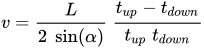
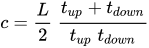
where {\displaystyle v}

With wide-beam illumination transit time ultrasound can also be used to measure volume flow independent of the cross-sectional area of the vessel or tube.[16]
Ultrasonic Doppler flow meters measure the Doppler shift resulting from reflecting an ultrasonic beam off the particulates in flowing fluid. The frequency of the transmitted beam is affected by the movement of the particles; this frequency shift can be used to calculate the fluid velocity. For the Doppler principle to work there must be a high enough density of sonically reflective materials such as solid particles or air bubblessuspended in the fluid. This is in direct contrast to an ultrasonic transit time flow meter, where bubbles and solid particles reduce the accuracy of the measurement. Due to the dependency on these particles there are limited applications for Doppler flow meters. This technology is also known as acoustic Doppler velocimetry.
One advantage of ultrasonic flow meters is that they can effectively measure the flow rates for a wide variety of fluids, as long as the speed of sound through that fluid is known. For example, ultrasonic flow meters are used for the measurement of such diverse fluids as liquid natural gas (LNG) and blood.[17] One can also calculate the expected speed of sound for a given fluid; this can be compared to the speed of sound empirically measured by an ultrasonic flow meter for the purposes of monitoring the quality of the flow meter’s measurements. A drop in quality (change in the measured speed of sound) is an indication that the meter needs servicing.
Coriolis flow meters[edit]
Using the Coriolis effect that causes a laterally vibrating tube to distort, a direct measurement of mass flow can be obtained in a coriolis flow meter.[18] Furthermore, a direct measure of the density of the fluid is obtained. Coriolis measurement can be very accurate irrespective of the type of gas or liquid that is measured; the same measurement tube can be used for hydrogen gas and bitumen without recalibration[citation needed].
Coriolis flow meters can be used for the measurement of natural gas flow.[19]
Laser Doppler flow measurement[edit]
A beam of laser light impinging on a moving particle will be partially scattered with a change in wavelength proportional to the particle’s speed (the Doppler effect). A laser Doppler velocimeter (LDV), also called a laser Doppler anemometer (LDA), focuses a laser beam into a small volume in a flowing fluid containing small particles (naturally occurring or induced). The particles scatter the light with a Doppler shift. Analysis of this shifted wavelength can be used to directly, and with great precision, determine the speed of the particle and thus a close approximation of the fluid velocity.
A number of different techniques and device configurations are available for determining the Doppler shift. All use a photodetector (typically an avalanche photodiode) to convert the light into an electrical waveform for analysis. In most devices, the original laser light is divided into two beams. In one general LDV class, the two beams are made to intersect at their focal points where they interfere and generate a set of straight fringes. The sensor is then aligned to the flow such that the fringes are perpendicular to the flow direction. As particles pass through the fringes, the Doppler-shifted light is collected into the photodetector. In another general LDV class, one beam is used as a reference and the other is Doppler-scattered. Both beams are then collected onto the photodetector where optical heterodyne detection is used to extract the Doppler signal.[20]
Calibration[edit]
Even though ideally the flowmeter should be unaffected by its environment, in practice this is unlikely to be the case. Often measurement errors originate from incorrect installation or other environment dependent factors.[21][22] In situ methods are used when flow meter is calibrated in the correct flow conditions.
Transit time method[edit]
For pipe flows a so-called transit time method is applied where a radiotracer is injected as a pulse into the measured flow. The transit time is defined with the help of radiation detectors placed on the outside of the pipe. The volume flow is obtained by multiplying the measured average fluid flow velocity by the inner pipe cross section. This reference flow value is compared with the simultaneous flow value given by the flow measurement to be calibrated.
The procedure is standardised (ISO 2975/VII for liquids and BS 5857-2.4 for gases). The best accredited measurement uncertainty for liquids and gases is 0.5%.[23]
Tracer dilution method[edit]
The radiotracer dilution method is used to calibrate open channel flow measurements. A solution with a known tracer concentration is injected at a constant known velocity into the channel flow. Downstream the tracer solution is thoroughly mixed over the flow cross section, a continuous sample is taken and its tracer concentration in relation to that of the injected solution is determined. The flow reference value is determined by using the tracer balance condition between the injected tracer flow and the diluting flow. The procedure is standardised (ISO 9555-1 and ISO 9555-2 for liquid flow in open channels). The best accredited measurementuncertainty is 1%.[23]
See also[edit]
—
Sincerely, Hengki Setiawan
PT. PANEN RAYA DIESEL
Kencana Tower, 2nd Floor
Meruya ilir No. 88, Jakarta Barat 11620.
email : setiawan.prd@mail.com
Phone / Fax : (021) – 26051249
Mobile : +62-8111746611
For More Information, please visit us @ http://www.panenraya.id
Note : Email more than 1GB please send to : panenrayadiesel@gmail.com